
|
|
1190.2. Definitions
1190.3. Functional Classification
1190.4. General Principles
1190.5. Control Dimensions
| 1190.1. General |
Driveways that intersect public roadways are a type of at-grade intersection. The numbers of accidents at driveway intersections are disproportionately higher than at public road intersections and consequently, driveway intersection design merits special attention.
The regional director or his or her designee may grant exceptions on driveways to be constructed or reconstructed along existing highways built to design standards prior to the AASHTO A Policy on the Geometric Design of Highways and Streets 2001. Driveways to be constructed or reconstructed along highways built according to the AASHTO A Policy on the Geometric Design of Highways and Streets 2001, must follow the procedures of Section 1100.3. in the consideration of waivers from the driveway standards.
Municipal geometric standards approved for use on Department roadways within a municipality should be used instead of the geometric standards contained in this section for all driveways within the municipality.
The regional director will grant approval of municipal driveway geometric standards for use on roadways administered or maintained by the Department after review by the following people:
- Regional preconstruction engineer
- Regional director of maintenance and operations
- Headquarters chief engineer of Statewide Design and Engineering Services
| 1190.2. Definitions (See Figures 1190-1 through 1190-7b) |
Angle of Intersection: The horizontal angle of 90 degrees or less between the driveway centerline and the edge of the traveled way of the public roadway
Buffer Area: The border area along the property frontage between the edge of traveled way and the right-of-way line bounded at each end by the frontage boundary lines
Collector-Distributor Road: An arterial road (usually one-way, with limited access) auxiliary to and adjacent to the side of a freeway for collection or distribution of traffic entering or leaving the freeway
Clear Zone: The roadside border area, starting at the edge of the traveled way, available for safe use by errant vehicles. Establishment of clear zone implies that rigid objects and other hazards with clearances less than the minimum width should be removed, relocated to an inaccessible position or outside the minimum clear zone, remodeled to make safely traversable or breakaway, or shielded.
Corner Clearance: The distance along the edge of traveled way of a public road or street from the near edge of traveled way of another public road or street to the tangent projection of the nearest edge of any driveway, not including transition slopes, tapers, or return-radii
Distance Between Driveways: The distance measured parallel to the centerline of roadway between intersection of the inside edges of two adjacent driveways and the right-of-way line
Driveway Foreslope: In cross-section, that portion of the driveway embankment that slopes downward from the driveway
Edge Clearance: The distance measured along the edge of traveled way between the frontage boundary line and the tangent projection of the nearest edge of driveway, not including returns, flares, or transition
Frontage: The length along the road or street right-of-way line of a single property tract, measured parallel to the centerline of the road or street, between the edges of the property. Corner property at a road or street intersection has a separate frontage along each road or street.
Frontage Boundary Line: A line perpendicular or radial to the public road or street centerline at each end of the frontage, extending from the right-of-way line to the edge of traveled way
Frontage Road: A local road auxiliary to and adjacent to the side of an arterial highway for service to abutting property and adjacent areas and for control of access
Interchange Ramp: A turning roadway at an interchange for travel between intersecting legs
May: A term indicating permission. There is no requirement for design or application.
Return: The curbed or uncurbed edge of the road, street, or driveway intersection that connects the edge of the public roadway with the adjacent edge of the driveway or another public roadway; usually as a single radius
Right-of-Way (ROW): A strip of land owned by a municipality or the state upon which a public road is constructed
Setback: The distance measured perpendicular or radial to the right-of-way line and the nearest building, pump island, display stand, or other manmade object over 6 inches in height within the property
Shall: Where requirements in the design standards are described with the “shall” or “must” stipulation, it is mandatory that these requirements be met.
Should: An advisory term. Where the word “should” is used, the specific design criteria are recommended, but they are not mandatory. However, you should document why you did not follow the recommended criteria.
Width: The distance across the driveway at its narrow point within the right-of-way measured at right angles to the centerline of the driveway
Back to top| 1190.3. Functional Classifications |
Highways, roads, and streets are classified according to their intended function as arterials, collectors, or local roads or streets. Arterials are primarily, if not exclusively, for through traffic along the roadway. Local roads and streets are primarily, if not exclusively, to provide access to the public road system from the property adjacent to the roadway. Collectors serve as limited through traffic ways and to provide access from the adjacent property. For safety and efficiency, arterials should have few, if any, private driveways.
Freeways and expressways are special, high-design-type arterials that are exclusively for through traffic. Access is legally controlled along the arterial and no private driveways are permitted.
Driveways will not be allowed on other arterials if other access is available. The Department’s primary concern is the safe, efficient movement of through traffic. If driveways directly accessing the arterial are necessary then their number, location, and design will be controlled to minimize the effect on through traffic.
On local roads and streets, the roadway’s primary purpose is to provide access to adjacent lands. Consequently, the Department only exercises driveway controls that are necessary to a safe roadway. Collector roadways require more driveway controls than local roads and streets, but less than arterials.
Where there are differences in the required degree of control for driveway design and placement due to variance in functional classes, differing criteria are provided. The process of formally classifying Alaska roadways is not complete. If a particular roadway is not classified, the regional director or his or her designee will determine the interim classification for administering the driveway design standards.
Back to top| 1190.4. General Principles |
1. Buffer Area: Buffer areas should be graded and landscaped to ensure adequate sight distance along the roadway, proper drainage, adequate clear zones, and a good appearance.
2. Sight Distance: The profile grade of a driveway and the treatment of the buffer area should allow the driver on the driveway to see sufficiently along the roadway to enable entry to the roadway without creating a hazard, and without encroaching into the traveled way (See Figure 1190-1).
3. Setbacks: The location of improvements on private property adjacent to the right-of-way line should not require parking, stopping, and maneuvering of vehicles within the right-of-way for vehicles or patrons to be properly served.
4. Location of Driveways: The location of driveways must minimize interference with the free movement of normal roadway traffic. This will reduce the hazards caused by congestion. Do not place driveways adjacent to or within an intersection. They also should not be located on a separate turning roadway, auxiliary speed change lane, or exclusive turning lane. Driveway placement must not provide direct access to the through roadways, ramps, or collector-distributor roadways of a freeway or expressway.
5. Number and Arrangement of Driveways: The number of driveways provided to a property should be the minimum required to adequately serve the needs of that property. Frontages of 50 feet or less must be limited to one driveway per frontage. Not more than two driveways should be provided to any single property tract or business establishment, but where the single ownership frontage exceeds 1,000 feet, additional driveways may be allowed provided they are required for servicing the property, and the distance between adjacent driveways is at least 330 feet.
Where two driveways are provided for one frontage less than 1,000 feet long, the clear distance between driveways should not be less than the minimum distances presented in 1190.5., Control Dimensions. Corner clearances at intersections should also be in accordance with the distance shown in 1190.5.
Develop driveways and adjacent property so that vehicles entering any arterial or collector roadway are not required to do so by backing into the right-of-way. Develop all frontages having two or more driveways and all commercial developments so that backing into a public roadway isn’t necessary. Multi-family residential developments of more than four units per lot are considered commercial development as far as driveway standards are concerned.
7. Drainage: Construct all driveways and buffer areas so that there will be no right-of-way surface drainage onto the traveled way of the public roadway. Where driveways are on the high side of a superelevated roadway, or are otherwise on a descending grade into the edge of traveled way, special drainage structures, including drop inlets or slotted drains, may be required to prevent non-right-of-way drainage from flowing into or across the public roadway traveled way. It is the responsibility of the property owner or permittee to maintain these drainage structures.
In addition, design and construction of the driveway and buffer must not impair or alter drainage within the right-of-way, which may damage or threaten the stability of the public roadway. All drainage facilities within the right-of-way must conform to any applicable Department standards.
9. Lighting: The Department will not provide roadway illumination solely for private driveways. The adjacent property owner may, except as stated here, opt to install such lighting as long as it conforms to accepted highway lighting criteria as set forth in the AASHTO publication An Informational Guide for Roadway Lighting. A property owner may not illuminate a driveway if it is within 500 feet of an unlit public road intersection.
10. Anticipated Traffic: It is not necessary to estimate the volume of traffic for the majority of driveways. However, for larger developments it may be desirable, if not necessary, to do so to determine the number, size, and design of the driveways needed to serve the development. A few well-designed driveways are preferable to many smaller driveways.
When the volume of traffic is expected to exceed 100 vehicles during the peak hour, a competent licensed professional engineer should conduct an analysis of the vehicle trip generation characteristics of the development. If such an analysis is not available, you may use the average trip generation factors in Table 1190-1, which are based upon the Institute of Transportation Engineers Informational Report, Trip Generation, 3rd Edition, to determine anticipated traffic for establishing the number, size, and design of driveways needed to accommodate the development.
“Peak hour” is the peak traffic-generating hour of the off-street facility.
|
Table 1190-1
|
|
|
Average Trip Generation Factors *
|
|
| Apartments and other residential units | 1.00 trips per dwelling unit |
| Hotels and motels | 1.00 trips per room |
| Schools (All) | 0.25 trips per student |
| Industrial facilities | 0.50 trips per employee |
| Hospitals | 1.36 trips per bed |
| Nursing homes | 0.36 trips per bed |
| Clinics | 2.48 trips per 1,000 sf* |
| General office buildings | 2.00 trips per 1,000 SF |
| Medical office buildings | 3.90 trips per 1,000 SF |
| Civic centers | 2.85 trips per 1,000 SF |
| Post offices, motor vehicle offices and other high-turnover public services | 11.00 trips per 1,000 SF |
| Discount stores | 6.97 trips per 1,000 SF |
| Hardware stores | 5.20 trips per 1,000 SF |
| Shopping centers, per feet squared |
|
| 0-50,000 SF |
 |
| 50,000-1,500,000 SF |
|
| Service stations |
6.00 trips per pump (two hoses) |
| Car wash |
132.00 trips per site |
| Truck stop |
88.00 trips per site |
| Supermarket |
15.7 trips per 1,000 SF |
| Convenience market |
47.0 trips per 1,000 SF |
| Wholesale markets |
0.52 trips per 1,000 SF |
| Furniture stores |
0.10 trips per 1,000 SF |
| Banks |
30.00 trips per 1,000 SF |
| Savings & Loan offices |
9.70 trips per 1,000 SF |
| Insurance offices |
2.40 trips per 1,000 SF |
|
* Average number of one-way trips generated (or attracted) by a given facility during the peak generating (or attracting) hour of the facility. This peak may or may not coincide with peak traffic flow on the adjacent street. Where the average time of the motorist at the generator (or attractor) is less than one hour, the flow is half into the facility and half out. (Example: Truck stops with 88 peak hour trips per site would represent 44 inbound and 44 outbound trips.) Trips based on area are based on gross leasable floor area. |
|
11. Median Openings: Where a median exists or is to be constructed on a public roadway, driveways should be designed and controlled to allow right turns only. Median openings should not be provided for driveways unless all the following conditions exist:
a. There is a sufficient volume of traffic using the subject driveway to warrant driveway intersection design as a public intersection
b. The driveway intersection is evenly spaced between adjacent arterial or collector intersections
c. Installation of a signal at present or in the future at the subject driveway intersection will not adversely affect the capacity of the public roadway
In order to minimize wrong way movements on the divided public roadway, driveways planned near a median opening should be placed either directly opposite the median opening or at least 200 feet from the median opening.
12. Design Vehicles: Refer to AASHTO A Policy on the Geometric Design of Highways and Streets 2001, Chapter 2, Design Vehicles General Characteristics, for guidance in selecting the appropriate design vehicle for the driveway. At least one driveway shall have widths, intersection alignments, and corner radii designed to accommodate the turning paths of the largest vehicles generated by the site. This would include large single units or tractor-trailer combination vehicles that deliver freight.
Back to top| 1190.5. Control Dimensions |
Specific control dimensions implement the general principles in 1220.4. Exceed minimum dimensions to the extent possible. Due to differing conditions in rural and urban areas, different dimensions are provided. Where appropriate, the control dimensions also reflect the difference between differing functional classes of roadways.
In administering these driveway standards, urban areas have populations of 500 or more within a defined compact area. The defined area need not be incorporated, but an incorporated place containing 500 people would be an urban area. Unincorporated places that have the characteristics of an incorporated community of 500 should be considered urban. In addition, if a roadway has urban characteristics such as small lot frontages, you may use the urban control dimensions.
1. Sight Distances: Figure 1190-1 illustrates the unobstructed sight distance along the public roadway, which should be available to a motorist entering the roadway. On arterial collector roadways, if the appropriate sight distance cannot be reasonably achieved, relocate the driveway.
The sight line used to set sight distance is from the entering height of eye (3.5 feet above the driveway surface) to the driver eye height of the design vehicle (3.5 feet above the surface of the public roadway at the required distance from the driveway). The driver’s eye is assumed to be between 14.4 to 17.8 feet from the edge of the nearest through traveled way, and the triangle formed by the sight lines left and right from this point to the required sight distances left and right along the public roadway is the sight distances triangle. Nothing should substantially obstruct the entering driver’s view of public roadway traffic anywhere within this triangle.
The return radii for driveways using returns, curbed or uncurbed, should conform to Table 1190-2.
5. Curb Cuts: The bottom width of curb cuts should equal the width of driveway and should match the flow line (or bottom of curb face line) of the curb section at the edge of roadway. Transitional slopes should begin at the edge of driveway and slope upward to reach the top of a 6-inch-high curb face in 6 feet. The transitional slopes behind the curb face may have a constant width with a variable slope or a constant slope with a variable width.
6. Distance between Driveways: The minimum distance between two adjacent driveways, on the same parcel, measured along the right-of-way line between the adjacent edges, should conform to Table 1190-3.
7. Setback: Setback distances must conform to local zoning requirements. Where local zoning ordinances do not provide a minimum setback, the minimum setback should be 16.5 feet, and where angle parking is permitted adjacent to the right-of-way line, the setback should be 50 feet.
9. Corner Clearance: The minimum distance from the nearest face of the curb, or nearest edge of traveled way for uncurbed roadways, of an intersecting public roadway to the nearest edge of driveway should conform to Table 1190-4.
a. Driveway with Uncurbed Returns: Public roadway with a negative cross-slope (i.e. outer edge of traveled way lower than lane or centerline):
- From the outer edge of the traveled way to the edge of the shoulder or 9 feet, whichever is greater, the driveway profile grade should be the same as the traveled way or shoulder cross-slope.
- From the outer edge of the shoulder, a vertical curve should connect the profile to a positive or negative grade, which will bring the driveway profile to the adjacent property grade.
b. Driveway with Curbed Returns: Public roadway with a negative cross-slope (i.e. outer edge of traveled way lower than lane or centerline):
- Beginning with an angle point at the flow line (bottom of face of curb) along the roadway, the driveway profile should rise at a gradient such that the algebraic difference in grade between the cross-slope of the roadway and the grade of the driveway does not exceed 8 percent.
- A landing zone must begin after a rise of 6 inches.
c. Driveway with Returns: Public roadway with positive cross-slope (i.e., on high side of superelevated section):
- From the outer edge of traveled way to the edge of the shoulder or 8 feet, whichever is greater, the driveway profile grade should be the same as the traveled way superelevation rate.
- From the outer edge of the shoulder, a vertical curve should connect the profile to a positive or negative grade, which will bring the driveway profile to the adjacent property grade
d. Driveway with Curb Cuts
- From the bottom face of curb or flow line, the driveway profile grade should slope uniformly upward at a grade not to exceed an algebraic difference of 8 percent with the adjacent lane or shoulder cross-slope.
- If a sidewalk or portion thereof remains to be crossed, the driveway profile may match the surface of the sidewalk.
- The profile should then follow a vertical curve or have an angle point, if necessary, to connect with a positive or negative grade, which will bring the driveway profile to the adjacent property grade.
e. Vertical Curves: Vertical curve should be symmetrical and as flat as feasible. Crest vertical curves should not exceed a 3¼-inch hump in a 12-foot chord, and sag vertical curves should not exceed a 2-inch depression in a 12-foot chord. Vertical curves must not have humps or depressions exceeding 3.6 inches in a 12-foot chord.
f. Landings: All driveways are to have landing zones. Landing length depends on anticipated traffic. Passenger cars require 12 feet minimum while semi-tractor trailers require 30 feet based on wheel bases.
g. Pedestrian Areas: Where curbed returns intersect a pedestrian way, provide appropriate handicapped access ramps.
11. Speed Change Lane and Left-Turn Lanes: On high-speed (50 mph or over) or high-volume arterial roadways, speed change lanes may be required for the acceleration or deceleration of vehicles entering or leaving the public roadway from or to a higher-volume traffic generation (greater than or equal to 100 vehicles per hour) or attracting development. Use Figure 4-3 of NCHRP 279 Intersection Channelization Design Guide as a guideline for the right-turn treatments. On a one-way street, the above criteria also apply to the left through lane. For guidelines on the need for left-turn lanes on a main street or road at a driveway, refer to Exhibit 9-75 in AASHTO A Policy on the Geometric Design of Highways and Streets 2001.
|
Table 1190-2
Driveway Return Radii (feet) |
||||||
|
Driveway
|
Residential
|
Farm
|
Commercial
|
|||
|
Width (ft)
|
Curbed
|
Uncurbed
|
Curbed
|
Uncurbed
|
Curbed
|
Uncurbed
|
|
14 - 20
|
*20
|
20
|
-
|
20
|
-
|
-
|
|
24 - 34
|
-
|
-
|
-
|
40
|
*40
|
40
|
| * For curbed roadways where residential driveways or commercial driveway have a 100-vehicles-per-hour or fewer repetitive peak, use a curb cut rather than a return. | ||||||
|
Table 1190-3 Distance Between Driveways (on same parcel) |
|||
|
Hourly Volume > 10 vph
|
|||
|
Speed (mph)
|
Rural Arterial and Collector Roads
|
Urban Arterial and Collector Streets
|
Urban and Rural Local Streets and Roads
|
|
30
|
370 feet
|
200 feet
|
200 feet
|
|
35
|
400 feet
|
260 feet
|
250 feet
|
|
40
|
440 feet
|
340 feet
|
310 feet
|
|
45
|
540 feet
|
430 feet
|
390 feet
|
|
50
|
690 feet
|
510 feet
|
490 feet
|
|
Hourly Volume Less than or equal to 10 vph
|
|||
|
Functional Classification
|
Distance
|
||
|
Arterial roadways
|
75 feet
|
||
|
Collector roadways
|
50 feet
|
||
|
Local roadways
|
35 feet
|
||
Table 1190-4
Corner Clearance
|
Hourly Volume less than or equal to 10 vph
|
|||
|
Corner Clearance (Feet)
|
|||
|
Functional Classification
|
Curbed Crossroad
|
Uncurbed Crossroad
|
|
|
Urban
|
Rural
|
||
|
Arterial roadways
|
60 feet
|
70 feet
|
100 feet
|
|
Collector roadways
|
50 feet
|
60 feet
|
60 feet
|
|
Local roadways
|
40 feet
|
50 feet
|
60 feet
|
|
Hourly Volume > 10 vph
|
|||
|
Speed (MPH)
|
Major Generator >250 vph
|
Medium Generator 100 - 250 vph
|
Small Generator <100 vph
|
|
30
|
200 feet
|
150 feet
|
80 feet
|
|
35
|
260 feet
|
210 feet
|
110 feet
|
|
40
|
330 feet
|
260 feet
|
150 feet
|
|
45
|
390 feet
|
310 feet
|
180 feet
|
|
50
|
460 feet
|
340 feet
|
230 feet
|
Driveway Sight Distance
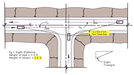
Figure 1190-1
Sight Distance
|
DESIGN SPEED or POSTED SPEED LIMIT mph
|
SD MINIMUM (ft)
|
|
20
|
115
|
|
25
|
155
|
|
30
|
200
|
|
35
|
250
|
|
40
|
305
|
|
45
|
360
|
|
50
|
425
|
|
55
|
495
|
|
60
|
570
|
|
65
|
645
|
Note: Minimum sight distances are stopping sight distances for level grades, between –3% and +3%. Refer to AASHTO A Policy on the Geometric Design of Highways and Streets 2001, for desirable intersection sight distances and for grade adjustments.
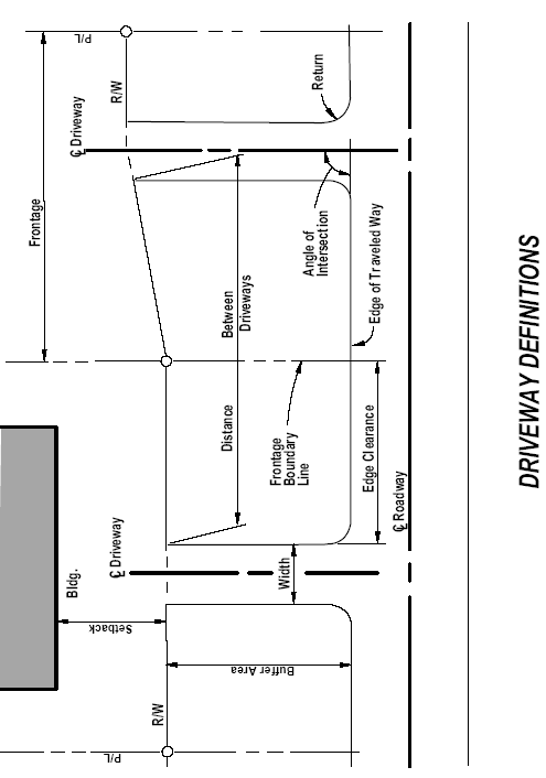
Figure 1190-2
Driveway Definitions
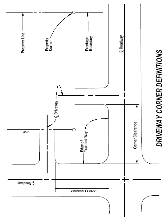
Figure 1190-3
Driveway Corner Definitions
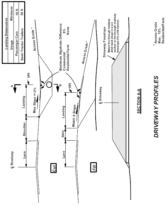
Figure 1190-4
Driveway Profiles
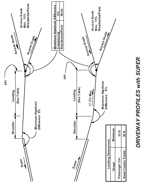
Figure 1190-5
Driveway Profiles With Super
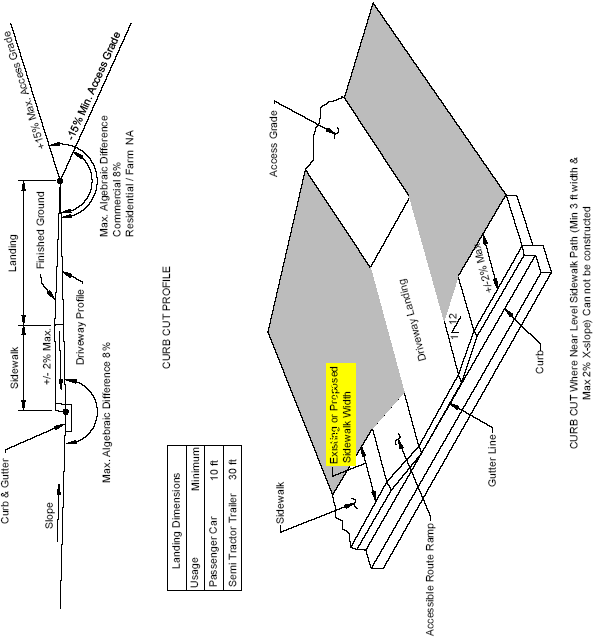
Figure 1190-6a
Curb Cut Profile
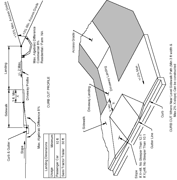
Figure 1190-6b
Curb Cut Profile
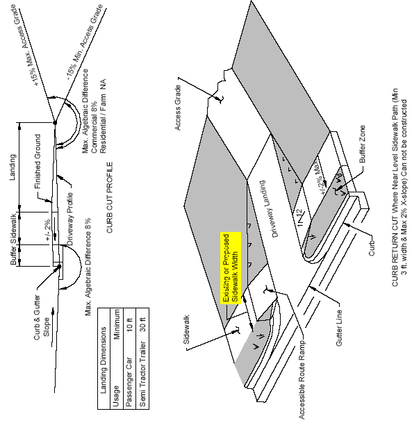
Figure 1190-7a
Curb Cut Profile
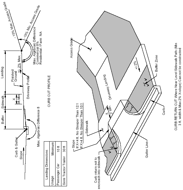
Figure 1190-7b
Curb Cut Profile